Naming stuff is one of the core decisions one has to take while designing an architecture. It might not look as important as utilising the right pattern in the right place or defining your database model but my experience says that a good naming convention helps identifying design flaws.
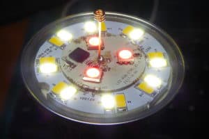
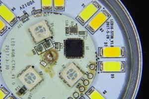
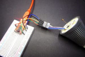
In a previous post I introduced the network I’m building for my home monitoring system. As I said it will be based on MQTT, a lightweight messaging protocol. An MQTT message has 4 attributes: topic, value, QoS and retain value. I will focus on the “topic” in this post but I will come back to the QoS and retain attributes sometime in the future.
The MQTT specification defines topic as “(…) the key that identifies the information channel to which payload data is published. Subscribers use the key to identify the information channels on which they want to receive published information”. But the cool thing about MQTT topics is that the protocol defines a hierarchy structure very much like the Filesystem Hierarchy Standard in use in unix, linux and mac boxes. This, along with the possibility of using wildcards to match topics, makes this structure very suitable for a WSN.
Some examples of topics are:
- /home/llivingroom/bulb1/status
- /home/door/sensor/battery
- /home/door/sensor/battery/units
- /home/outdoors/temperature
- /home/outdoors/temperature/yesterday/max
- /zigbee/0013a20040401122/dio3
- /zigbee/0013a20040410034/adc7
- …
Semantic vs. physical approach
There is a bunch of small decisions to take here. Let’s start from the beginning… When building a topic hierarchy there are two different approaches (at least). Using a semantic approach and name things for where they are and what they measure. A humidity sensor in the bathroom to detect shower times (??) could publish its data under “/home/bathroom/humidity”.
The second option is a physical approach and name things for what they are or what they are attached to. Like in the previous example the humidity sensor might be attached to the analog pin 3 of an end device radio in a Xbee mesh network, so it could as well publish its data under “/xbee/0013a20040410034/adc3″, why not?
Generally the semantic approach is preferable since it is more human friendly but the physical approach is more machine friendly (even if only slightly). Using again the previous example, the Xbee gateway could subscribe to “/xbee/+/+/set” to get all the messages that should be sent to the different radios.
Semantic approach structure
For the physical network it is easy to define a topic structure based on the path to get to the data, like in the last example: “the sensor attached to the AD converter pin 3 in the radio with address 0×00 0×13 0xa2 0×00 0×40 0×41 0×00 0×34″.
For the semantic approach there are a bunch of possibilities but most of the networks out there use a location based structure: first you physically identify the sensor by its location and then the magnitude: “/home/2ndfloor/bathroom/temperature”. As you can see this can be read quite naturally, albeit reversed: “the temperature in the bathroom of the 2nd floor at home”.
It’s worth noting that MQTT provides a way to split a large scale networks into different chunks, each with it’s own scope, via the mount_points feature. Check an interesting thread about mount_points here. So it can be a good idea to foresee how my network might grow, not only downwards but also upwards, and that’s why the “/home” in some of the examples I’m showing might not be a good root location, better use something more specific like “/buckingham palace” or “/lovenest” (I will keep using /home in the examples anyway).
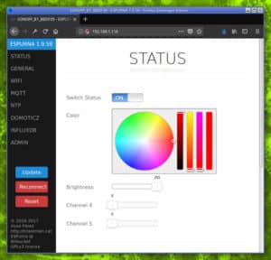
And after the location part I will just provide the magnitude: temperature, pressure, humidity, air_quality, power, battery,… and status. Status is normally a discrete value (typically 0 or 1) indicating the state of the sensor or device. I find it preferable to use “/home/entrance/light/status” that simply “/home/entrance/light” to publish whether the lights are on or off.
Modifiers, prefixing and postfixing
I have already used some “particles” in the example topics above, words like ‘set’, ‘yesterday’, ‘max’,… I’ve gathered some of these particles browsing the internet searching for MQTT topic names. I have tried to classify them into different types:
- Metadata: timestamp, units, alarm,…
- Agregation: time ranges like today, last24h, yesterday, month, year, ever,… and operators like max, min or average. A special case of time range could be “now”, “last” or “current” for the last value published on a certain topic although it is usually omitted.
- Actions: get or query, set
- Structure-related: raw for, well, raw values
Some of the modifiers are clearly attributes or metadata of the data itself. In these cases postfixing makes perfect sense:
- /home/bedroom/temperature 21
- /home/bedroom/temperature/units C
- /home/bedroom/temperature/timestamp 2012-12-10T12:47:00+01:00
The reading from the bedroom temperature sensor was 21 celsius on Dec 10 at 12:47 UTC+1. As I’ve said, some people uses “current”, “now” or “last”. I used to think this as redundant but it may be necessary when graphing your network messages the way Ben Hardill explains in his d3 MQTT topic tree visualiser post, where only the leaves can have values.
Another reason to use “last” (or any of the others) is when you are also publishing aggregated information for that magnitude. In this case it looks more logical to have a structure like this one:
- /home/bedroom/temperature/last
- /home/bedroom/temperature/last/timestamp
- /home/bedroom/temperature/last24h/max
- /home/bedroom/temperature/last24h/max/timestamp
- /home/bedroom/temperature/last24h/min
- /home/bedroom/temperature/last24h/min/timestamp
- /home/bedroom/temperature/ever/max
- …
But first you should ask yourself if your messaging network is the place to publish this info. Who will use it? If the answer is only you then you should add some graphing solution like Cosm, Nimbits, Open Sen.se, or your own. Keep in mind MQTT is a Machine to machine protocol.
But for actions and structure modifiers it’s not so evident. Postfixing (appending at the end) for actions is coherent with the “reversed natural reading” naming convention: “switch on the lights in the stairs” will be a “/home/stairs/light/status/set 1″.
But prefixing in MQTT is equivalent to creating new hierarchy roots, thus “splitting” the topics into different sub-networks, so it fits quite well for structure modifiers. You could have a /home root for sensor data using a semantic approach and a /raw root for raw sensor data using a physical approach. The network should then provide a service to map topics back and forth between both sub-networks:
- /raw/xbee/0013a20040410034/adc3 => /home/bedroom/temperature
- /home/bedroom/lights/set => /raw/xbee/0013a20040410034/dio12
This republishing service has been proposed by Robert Heckers in his MQTT: about dumb sensors, topics and clean code post and you can even use an open source implementation of an MQTT republisher by Kyle Lodge using the Mosquitto python library.
Republishing vs. publishing the right contents
There are some details I don’t like about the “republishing” approach. First you are setting up a service that will have to know about the physical network (gateways, technologies, radio addresses, pins…). Second you are doubling the traffic in your network without adding any more value apart from the topic renaming.
So my point is to make the mapping in the gateway before publishing anything. This way the messaging is agnostic of the physical structure of the radio network, the gateway is the only holder of that information. Besides, the mapper will double as a filter, filtering out unnecessary messages *and* processing values. Let’s say you configure a MCU-less sensor with an Xbee radio to report the input of an analog pin. Chances are you will have to do some maths with the reported value to get a meaningful one. For example, the supply voltage reported by the radio has to been scaled by 1200/1024 to get the actual value in mV.
Conclusions
To be honest, I’ve written this quite large post to make up my mind about the subject. These are some of the conclusions I will apply to my own system:
- The message topics should be independent from the underlying technology.
- Topics will have semantic meaning, starting with the location and then the magnitude they represent. More particles can be added to the topic to add attributes or metadata.
- The different gateways and publishers will be responsible for:
- Abstracting the physical network architecture.
- Filtering unnecessary messages.
- Processing values before publishing them.
- Adding metadata.
- Listening and processing messages aimed to sensors under their “control”.
- Republishing will be avoided if possible.
- Aggregation data goes somewhere else.
I am not really sure about publishing content only to leaf nodes. The analogy with a linux file system is quite obvious: you only put content into leaf nodes (files), but still I find it somewhat ugly (and for me that means there is something wrong).
The final test will be to actually apply this rules to implement my MQTT topics hierarchy to see if it works. Let’s go!